| Analog-to-digital converters
|
|
When measuring quantities of different nature, both constant and changing in time, one often tries to
convert them into electric voltages and currents. Electric signals can be easily transmitted from remote
sensors. There is an "arsenal" of standard devices and techniques for their processing. Previously,
measured values were fixed by deflections of galvanometer needles, traces of paint on the tape of
self-recorders, luminescence on the oscillograph screen. Modern measurement systems represent data,
as a rule, in a digital form with the use of special transistor devices - analog-to-digital
converters (ADC). The task of an analog-to-digital conversion consists in the transformation of the
input voltage at the instant of measurement into a proportional value; if the voltage alternates
then it is transformed into a discrete sequence of values.
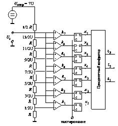
Let us consider principle of ADC functioning with the example of the scheme shown in the Figure.
It realizes so-called parallel approach: input voltage Uc is compared simultaneously
to n reference (etalon) voltages which are formed with the aid of resistive potential divider
Uref. The number of the reference voltages and an interval between
their values are determined by the range of the measured values and required accuracy of the
conversion - the number of binary digits of a value at the device output. Thus, one seven equidistant
etalon voltages for the 3-bit representation which is realized in the considered example and
allows to record eight different numbers including zero.
 The measured voltage Uc is compared to the etalon levels with the aid of seven
comparators ki whose input voltages take the values regarded
equal to
- 1 (binary) if the voltage at the input point (+) exceeds the voltage at the input point (-)
- and 0 otherwise.
Thus, if the measured voltage does not fall outside the range [5U/2, 7U/2] then the
comparators with numbers 1-3 are set into the state "1" and the comparators with numbers 4-7 -
into the state "0". A special logical scheme (priority encoder) converts these states into a
binary number z1z2z3 (011 in our example) or corresponding decimal
number (3 in our example). If the voltage changes in time then one stores instantaneous value of
the voltage at the input of comparators using selection-storage circuit shown by rectangles on
the scheme and retain them constant during the measurement interval. Measurement instants are
dictated by special tact signals; if they are periodic, then one gets an equidistant sequence of
binary values (time series) at the output of the encoder. The described parallel approach to the
realization of analog-to-digital conversion is simple but non-economical. Therefore, better
approaches have been developed and are widely used, e.g., weighted and numerical.
|


